Sensing distance
Supply voltage
Output
12 to 24 VDC
80 mA
100 mA
3 to 10 cm, 5 to 25 cm
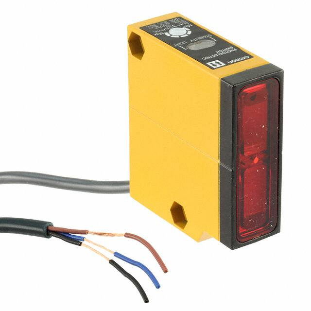
Photoelectric Sensor
E3S-LS
Focusable Sensors with Built-in DC
Amplifiers
Pinpoint focusable and area focusable models
eliminate background objects.
Ideal for precise detection of level/height, edges,
small holes and openings, objects touching one
another, objects inside transparent covers.
Ordering Information
Sensing method
Sensing distance
Model
NPN output
PNP output
Area focusable reflective
5 to 25 cm (continuously variable)
E3S-LS20XE4
E3S-LS20XB4
Pinpoint focusable reflective
3 to 10 cm (continuously variable)
E3S-LS10XE4
E3S-LS10XB4
3 ± 0.5 cm
E3S-LS3C1D
E3S-LS3RC4
---
Application Examples
E3S-LS10X
Sensing of objects utilizing
their difference in luster.
Sensing of objects traveling in
contiguous succession.
Sensing of small holes, narrow
openings, or unevenness.
Pencils
E3S-LS20X
Sensing of objects utilizing
their difference in luster.
Sensing of objects traveling in
contiguous succession.
Sensing of small holes, narrow
openings, or evenness.
ÉÉ
É
1
�E3S-LS
E3S-LS
Specifications
Ratings/Characteristics
Item
E3S-LS10Xj4
E3S-LS3C1D
E3S-LS3RC4
5 VDC –10% to
24 VDC +10%,
ripple (p-p): 10% max.
12 VDC –10% to
24 VDC +10%,
ripple (p-p): 10% max.
E3S-LS20Xj4
Power supply voltage
12 VDC –10% to 24 VDC +10%,
ripple (p-p): 10% max.
Current consumption
40 mA max.
Sensing distance
3 to 10 cm (variable
with distance
adjuster)
5 to 25 cm (variable
with distance
adjuster)
3±0.5 cm
Differential travel
0.5 mm max. at 3 cm
3 mm max. at 10 cm
5% max.
---
Standard objects
1 x 1 cm white mat
paper
5 x 7.5 cm white mat
paper
1 x 1 cm white mat paper
Load
Model with suffix -E4:
Model with suffix -B4:
80 mA max.
100 mA max.
30 mA max.
50 mA max.
Voltage
output
1.1 V max. at 80 mA
2 V max.
Control
output
ou
pu
DC
solid-state
so
dsae
Response time (ON, OFF)
1 ms max.
ON: 3 ms
OFF: 100 ms
1 ms max.
Sensitivity
Adjustable
---
Adjustable
Operation mode
Wire-selectable (Refer to “Output Circuit.”)
---
Wire-selectable
(Refer to “Output
Circuit.”)
Indicators
Light indicator (red), stability indicator (green)
Operation indicator
(red)
Light indicator (red)
Circuit protection
Short circuit
Provided
Mutual interference protection
Provided
---
Enclosure rating
IEC 144
IP67
IP40
NEMA
1, 3, 4X, 6, 12
---
Housing material
Metal
Light source
Red LED
Ambient temperature
Operating: –25 to 55 °C
2
Plastic
Infrared LED
Red LED
Operating: –10 to 55 °C
�E3S-LS
E3S-LS
Engineering Data
Excess Gain Ratio
E3S-LS10XE4
E3S-LS20XE4
E3S-LS3RC4
Peak receiver
output at 3 cm
Standard sensing object
(white paper)
Peak receiver
output at 10 cm
Operating
level
Sensing distance (cm)
Excess gain ratio
Excess gain ratio
Excess gain ratio
Peak receiver output at 5 cm
Sensing distance (cm)
Note:
Setting
distance
Standard sensing
object (black
carbon paper)
Operating
voltage
Sensing distance (cm)
1. Sensitivity adjustor: Set to MAX.
2. This graph shows the relationship between the
optical output and setting distance by adjusting
the sensitivity adjustor so that the optical output
will be maximum at a sensing distance of 3, 5, or
10 cm.
Operating Range
E3S-LS10XE4
E3S-LS3RC4
Standard object
(5 x 57.5 cm)
Distance: Min.
Distance X (cm)
Distance: Max.
Operating
distance x
Distance: 3 cm
Standard object
(1 × 1 cm)
Distance: 10 cm
Operating position Y (mm)
Optical axis
Operating position Y (mm)
Operating position Y (mm)
(with minimum sensing distance)
E3S-LS20XE4
Sensing object
size: 10 x 10 mm
Setting distance (mm)
Sensitivity
Short side
White mat paper
Long side
Distance (cm)
E3S-LS20XE4
Object sensed
Ratio of short side to long side = 2:3
Size of object (cm)
3
�E3S-LS
E3S-LS
Operation
Output Circuits
E3S-LS10X
-E4 Type (NPN Output)
-B4 Type (PNP Output)
+V
LightON
Brown
DarkON
+V
Blue
LightON
DarkON
Brown
Blue
Black
Black
Blue
Brown
2.2 Ω
Output
Main circuit
0V
Output
Black
Black
Blue
Brown
Main circuit
0V
E3S-LS20X
-E4 Type (NPN Output)
-B4 Type (PNP Output)
+V
LightON
Brown
DarkON
+V
Blue
LightON
DarkON
Brown
Blue
Black
Black
Blue
Brown
2.2 Ω
Output
Main circuit
0V
Output
Black
Black
Blue
Brown
Main circuit
0V
E3S-LS3C1D
Operation
indicator
(red)
Photoelectric
sensor main
circuit
+V
Brown
OUT
Black
Z
0V
Blue
Z: Zener diode (V2 = 30 V)
E3S-LS3RC4
Light-ON
Dark-ON
+V
Incident
indicator
(red)
OUT
Photoelectric
sensor main
circuit
0V
Brown
Black
Blue
Pink
4
Incident
indicator
(red)
Photoelectric
sensor main
circuit
+V
Brown
OUT
Black
0V
Blue
Pink
�E3S-LS
E3S-LS
Timing Chart
E3S-LS10X
-E4 Type (NPN Output)
-B4 Type (PNP Output)
Light-ON
Dark-ON
Incident
Interrupted
Light
Light-ON
Light
LIGHT
indicator
ON
OFF
LIGHT
indicator
Output
transistor
ON
OFF
Output
transistor
Operates
Releases
Load
(relay, etc.)
Load
(relay, etc.)
Dark-ON
Incident
Interrupted
ON
OFF
Operates
Releases
ON
OFF
H
L
Output voltage
(logic, etc.)
E3S-LS20X
-E4 Type (NPN Output)
-B4 Type (PNP Output)
Light-ON
Dark-ON
Incident
Interrupted
Light
Light-ON
Light
LIGHT
indicator
ON
OFF
LIGHT
indicator
Output
transistor
ON
OFF
Output
transistor
Operates
Releases
Load
(relay, etc.)
Load
(relay, etc.)
E3S-LS3C1D
Output
transistor
(load)
Operates
Releases
ON
OFF
E3S-LS3RC4
< T (See note)
Indicator
ON
OFF
H
L
Output voltage
(logic, etc.)
Sensing
object
Dark-ON
Incident
Interrupted
Light-ON
Light
Yes
No
T (See note)
ON
OFF
ON
OFF
3 ms max.
Note:
Timer setting
Timer setting
T = 0.1 to 1 s
LIGHT
indicator
ON
OFF
Output
transistor
ON
OFF
Load
(relay, etc.)
Dark-ON
Incident
Interrupted
Operates
Releases
(Between brown and
black lines)
5
�E3S-LS
E3S-LS
Dimensions
Note:
All units are in millimeters unless otherwise indicated.
E3S-LS10Xj4
E3S-LS20Xj4
Indicator
Cord:
4-mm dia., 18/0.12, 3-conductor
Standard length: 2 m
Weight: approx. 225 g
Two, M4 slotted
hexagonal bolts
Distance adjustor
Sensitivity
adjustor
Lens (14 x 47)
(A) (See note)
Mounting Holes
Emitter
Two, M 4 holes
Optical axis
8 dia.
Receiver
20
Two 4.4 dia.
holes
Note:
A mounting bracket can be attached to side A.
E3S-LS3C1D
E3S-LS3RC4
Indicator
Cord:
4-mm dia., 18/0.12, 3-conductor
Standard length: 2 m
Weight: approx. 60 g
E3S-LS3C1D Timer Volume
E3S-LS3RC4 Sensitivity Adjustor
8 dia.
Optical axis
Two, M3 holes
Optical axis
6
�E3S-LS
E3S-LS
Precautions
Sensing Distance Adjustment
E3S-LS10XE4
E3S-LS20XE4
Adjustment Method
1. Set the pointer of the sensitivity adjuster to the center of its
revolution range.
2. Turn the distance adjuster fully counterclockwise to the “S”
position.
3. Set the sensing object in position.
4. Turn the distance adjuster gradually clockwise to a point
where both the LIGHT and STABILITY indicators light. Fix the
distance adjuster at that point.
5. Adjust sensitivity.
Adjustment Method 1
When the quantity of light reflected from the object is greater than
that from the background object, adjust the sensing distance in the
following sequence:
1. Set the pointer of the sensitivity adjuster to the center of its
revolution range.
2. Turn the distance adjuster fully counterclockwise to the “S”
position.
3. Set the sensing object in position.
4. Turn the distance adjuster gradually clockwise to a point
where both the LIGHT and STABILITY indicators light. Fix the
distance adjuster at that point.
5. Adjust sensitivity.
ÉÉ
ÉÉ
É
É
É
Background object
Object sensed
Distance adjuster
ÉÉ
ÉÉ
ÉÉ
ÉÉ
ÉÉ
ÉÉ
Background object
Object sensed
Distance adjuster
Adjustment Method 2
When the quantity of light reflected from the object is greater than
that from the background object, adjust the sensing distance in the
following sequence:
1. Set the pointer of the sensitivity adjuster to the center of its
revolution range.
2. Turn the distance adjuster fully counterclockwise to the “L”
position.
3. Remove the sending object.
4. Turn the distance adjuster gradually clockwise to a point
where both the LIGHT and STABILITY indicators light. Fix the
distance adjuster at that point.
5. Adjust sensitivity.
7
�Read and Understand This Catalog
Please read and understand this catalog before purchasing the products. Please consult your OMRON representative if you have any questions or
comments.
Warranty and Limitations of Liability
WARRANTY
OMRON's exclusive warranty is that the products are free from defects in materials and workmanship for a period of one year (or other period if
specified) from date of sale by OMRON.
OMRON MAKES NO WARRANTY OR REPRESENTATION, EXPRESS OR IMPLIED, REGARDING NON-INFRINGEMENT, MERCHANTABILITY, OR
FITNESS FOR PARTICULAR PURPOSE OF THE PRODUCTS. ANY BUYER OR USER ACKNOWLEDGES THAT THE BUYER OR USER ALONE HAS
DETERMINED THAT THE PRODUCTS WILL SUITABLY MEET THE REQUIREMENTS OF THEIR INTENDED USE. OMRON DISCLAIMS ALL OTHER
WARRANTIES, EXPRESS OR IMPLIED.
LIMITATIONS OF LIABILITY
OMRON SHALL NOT BE RESPONSIBLE FOR SPECIAL, INDIRECT, OR CONSEQUENTIAL DAMAGES, LOSS OF PROFITS, OR COMMERCIAL
LOSS IN ANY WAY CONNECTED WITH THE PRODUCTS, WHETHER SUCH CLAIM IS BASED ON CONTRACT, WARRANTY, NEGLIGENCE, OR
STRICT LIABILITY.
In no event shall responsibility of OMRON for any act exceed the individual price of the product on which liability is asserted.
IN NO EVENT SHALL OMRON BE RESPONSIBLE FOR WARRANTY, REPAIR, OR OTHER CLAIMS REGARDING THE PRODUCTS UNLESS
OMRON'S ANALYSIS CONFIRMS THAT THE PRODUCTS WERE PROPERLY HANDLED, STORED, INSTALLED, AND MAINTAINED AND NOT
SUBJECT TO CONTAMINATION, ABUSE, MISUSE, OR INAPPROPRIATE MODIFICATION OR REPAIR.
Application Considerations
SUITABILITY FOR USE
OMRON shall not be responsible for conformity with any standards, codes, or regulations that apply to the combination of products in the customer's
application or use of the product.
At the customer's request, OMRON will provide applicable third party certification documents identifying ratings and limitations of use that apply to the
products. This information by itself is not sufficient for a complete determination of the suitability of the products in combination with the end product,
machine, system, or other application or use.
The following are some examples of applications for which particular attention must be given. This is not intended to be an exhaustive list of all possible
uses of the products, nor is it intended to imply that the uses listed may be suitable for the products:
• Outdoor use, uses involving potential chemical contamination or electrical interference, or conditions or uses not described in this catalog.
• Nuclear energy control systems, combustion systems, railroad systems, aviation systems, medical equipment, amusement machines, vehicles, safety
equipment, and installations subject to separate industry or government regulations.
• Systems, machines, and equipment that could present a risk to life or property.
Please know and observe all prohibitions of use applicable to the products.
NEVER USE THE PRODUCTS FOR AN APPLICATION INVOLVING SERIOUS RISK TO LIFE OR PROPERTY WITHOUT ENSURING THAT THE
SYSTEM AS A WHOLE HAS BEEN DESIGNED TO ADDRESS THE RISKS, AND THAT THE OMRON PRODUCT IS PROPERLY RATED AND
INSTALLED FOR THE INTENDED USE WITHIN THE OVERALL EQUIPMENT OR SYSTEM.
Disclaimers
CHANGE IN SPECIFICATIONS
Product specifications and accessories may be changed at any time based on improvements and other reasons.
It is our practice to change model numbers when published ratings or features are changed, or when significant construction changes are made.
However, some specifications of the product may be changed without any notice. When in doubt, special model numbers may be assigned to fix
or establish key specifications for your application on your request. Please consult with your OMRON representative at any time to confirm actual
specifications of purchased product.
DIMENSIONS AND WEIGHTS
Dimensions and weights are nominal and are not to be used for manufacturing purposes, even when tolerances are shown.
ERRORS AND OMISSIONS
The information in this catalog has been carefully checked and is believed to be accurate; however, no responsibility is assumed for clerical,
typographical, or proofreading errors, or omissions.
PERFORMANCE DATA
Performance data given in this catalog is provided as a guide for the user in determining suitability and does not constitute a warranty. It may represent
the result of OMRON’s test conditions, and the users must correlate it to actual application requirements. Actual performance is subject to the OMRON
Warranty and Limitations of Liability.
PROGRAMMABLE PRODUCTS
OMRON shall not be responsible for the user's programming of a programmable product, or any consequence thereof.
COPYRIGHT AND COPY PERMISSION
This catalog shall not be copied for sales or promotions without permission.
This catalog is protected by copyright and is intended solely for use in conjunction with the product. Please notify us before copying or reproducing this
catalog in any manner, for any other purpose. If copying or transmitting this catalog to another, please copy or transmit it in its entirety.
Cat. No. E39-E1-3
OMRON Corporation
2007. 3
In the interest of product improvement, specifications are subject to change without notice.
Industrial Automation Company
http://www.ia.omron.com/
(c)Copyright OMRON Corporation 2007 All Rights Reserved.
�